Multi-Contact MA210 Manuale d'uso
Pagina 6
Advanced Contact Technology
6 / 8 www.multi-contact.com
16
17
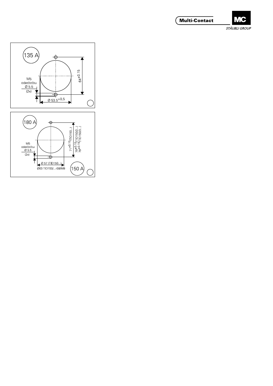
Montaggio del connettore
Assembly of plug connector
(ill. 16)
TID-S6/M5
Eseguire i fori in base al relativo
schema�
Avvitare la presa sul lato frontale della
superficie di montaggio.
(ill. 16)
TID-S6/M5
Drill holes according to drilling plan�
Screw receptacle on to front assembly
surface�
(ill. 17)
TID150-S8/M8, TID150/2-S8/M8,
TID150/3-S8/M8
Eseguire i fori in base al relativo
schema�
Avvitare la presa sul lato frontale della
superficie di montaggio.
(ill. 17)
TID150-S8/M8, TID150/2-S8/M8,
TID150/3-S8/M8
Drill holes according to drilling plan�
Screw receptacle on to front assembly
surface�
Montaggio della spina di col-
legamento
Assembly of plug connector
(ill 18)
Schemi di foratura per il montaggio
diretto delle spine singole S6���/S8���/
S12��� nelle prese di corrente del
trasformatore per il collegamento delle
spine flangiate TSB...
Coppia de serraggio:
S6 = 2,5 ±0,5 Nm,
S8 = 4,5 ±0,5 Nm,
S12 = 8 ±0,5 Nm
(ill. 18)
Drilling plan for the direct installation
of the individual plug pins S6���/S8���
/S12��� to the primary terminal board
of the transformer and for the installa-
tion of the panel mounting housings
TAG��� onto the plate of transformer�
Matching parts are flanged female
plugs TSB���
Tightening torque for individual plug:
S6 = 2,5 ±0,5 Nm,
S8 = 4,5 ±0,5 Nm,
S12 = 8 ±0,5 Nm