RISCO Group WL Door Window Contact RWT72I Manuale d'uso
Wireless door/window contact hi-security rwt72i
NORMALLY CLOSED
INPUT CONFIGURATION
Transmitter Terminal Block
NORMALLY OPEN INPUT
CONFIGURATION
Transmitter Terminal Block
DOUBLE END OF LINE
INPUT CONFIGURATION
Transmitter Terminal Block
7
Dipswitch Position
Internal Reed Switch (S1)
OFF
*
Disable
Enable
ON
8
To activate or deactivate function of anti- sabotage.
4
ON
Double transmission
Dipswitch Position
Transmission
Used to eliminate RF collision between detectors by repeating
the transmission
Single transmission
RF low power (when the transmitter
is close the receiver)
1. GENERAL DESCRIPTION
MAIN FEATURES
● Uses one of more than 16 million pseudo-randomaly selected
code addresses for setup (no DIP swiches).
●
Microprocessor design.
●
Extended battery life.
●
Selective fully supervised: 15 minutes.
●
Hold on/off
●
Selective response time:
Fast - for shock sensors
Slow - for magnetic switches, etc.
●
Selective wired input - N.C., N.O. or DEOL
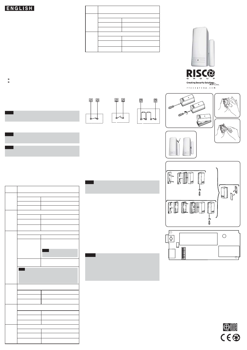
4. INPUT CONNECTION
Use the following diagrams for appropriate input termination
wiring.
For DEOL termination connect two 10K Ohm resistors (supplied)
as illustrated below.
INPUT TERMINATIONS
Place the unit at the highest possible position.
b. Temporarily attach the unit to this point using two sided adhesive
tape.
c. Generate an alarm signal (by momentarily opening or closing
the input terminals) and verify that the receiver has received the
signal. If the alarm signal is not detected, reposition the
RWT72I and try again.
8. FINAL MOUNTING
Separate the back part of the transmitter (Fig. 3), and mount
all the parts in place (Fig. 4).
If relevant, connect the sensor to the input terminals.
Notes:
1. The mark on the magnet's plastic case should be
opposite the mark on the transmitter's case (Fig. 5).
2. When installing the product, be sure that the back
tamper is correctly closed against the wall.
3. For installations on wood or alloy, the maximum
distance for normal operation is 10mm, while for metal
ferromagnetic materials (iron) it is 5mm.
●
Back & Cover tamper protection
2. OPERATIONAL MODES
NORMAL: The RWT72I transmits an alarm message when it is
triggered; when restored, it transmits a restoral message. Only
one alarm message is transmitted in any 2.5 minutes time slot.
Note:
Extra restoral message can be generated by reopening and
closing the inputs.
WRITE: A Write message will be transmitted by pressing both
tamper buttons (back and cover) for at least 3 seconds.
Note:
The unit sends a supervisory message every 15 minutes
indicating the input state and battery condition.
Note:
At installation or replacement, perform a Communication
Check with the receiver to verify proper operation.
LED INDICATION
After each detection, the LED turns ON momentarily.
On Low Battery condition - the LED will blink during each
transmission.
3. DIP SWITCH SETTINGS
The RWT72I has eight dipswitches:
6. TRANSMITTER/RECEIVER COMMUNICATION
SETUP
The RWT72I must identify itself to the system's receiver by writing
its coded message into the receiver's address memory. This is
accomplished by performing the following steps:
a. Set the receiver to Write Mode.
b. Remove the battery from the insulation material (Fig. 2).
Send a Write message pressing both tamper buttons (back and
cover) for at least 3 seconds. Verify that RWT72I has been
identified by the receiver.
c. Set the receiver to Normal Mode.
Note:
If for any reason it is necessary to re-send a write
message, press both of the tamper buttons (back and
cover) for at least 3 seconds.
7. SELECTION OF INSTALLATION LOCATION
a. Select a location best suited for communication
quality and near the intended wired detector (for switched sensor).
5. FRONT COVER REMOVAL (Fig. 1).
TECHNICAL SPECIFICATIONS
ELECTRICAL
Battery Type:
CR123 3V Lithium Battery
Current Consumption:
30μA standby; 13mA transmission
Frequency: 868.65
MHz
Dead Time (HOLD ON):
2.5 minutes
Supervision Transmission: Every 15 minutes
Modulation Type:
ASK
Battery Life:
5 years (Upon usage)
PHYSICAL Size:
81x35x32 mm (3.2 x 1.37 x1.27 in.)
ENVIRONMENTAL
RF immunity:
According to EN50130-4
Operating temperature:
-10°C to 55°C (14°F to 131°F)
Storage temperature:
-20°C to 60°C (-4°F to 140°F)
Specifications are subject to change without prior notice.
Should any questions arise please contact your supplier.
Dipswitch Position
ON
Hold Status
3
Dipswitch Position
Response Time
2
Dipswitch Position
External Sensor Mode
1
Normally Closed (NC)
Normally Open (NO)
Dipswitch
Number
Description
Dipswitch
Number
Description
Used to determine the external sensor mode.
Used to determine the transmitter response time.
Slow: 400 ms (For operation with
magnetic contacts, etc.)
Fast: 10 ms (For operation with a
shock sensor)
Used to determine the transmitter HOLD status.
Hold is On: There will be 2.5 minutes dead
time between the alarm detection
transmissions. (Restore messages will be
sent immiately).
Note:
Only one alarm message is
transmitted in any 2.5 minute period.
Hold is Off: No dead time between alarm
detection transmissions (the unit transmits
after each detection).
Note:
In both HOLD status the following occurs:
1. Disconnecting the detector’s input terminal will send an alarm
after 400 ms.
2. Reopening and closing the detector inputs will generate an
extra alarm and restore messages.
OFF
*
ON
10k
ALARM
TAMPER
10k
DETECTOR
ALARM
DETECTOR
ALARM
DETECTOR
6
5
ON
Enable DEOL
OFF
*
Dipswitch Position
ENABLE / DISABLE DEOL
Used to determine whether the external sensor input will be
DEOL or not.
Disable DEOL
ON
Dipswitch Position
Internal Reed Switch (S2)
OFF
*
Disable
Enable
To activate or deactivate function of RISCO Group magnet.
*
= Default
Used to determine the transmitter power
Dipswitch Position
RF Power Transmission
ON
OFF
*
RF high power
ON
●
Operates up to 1000 ft. (300m) range (outdoor)
Fig. 1
The RWT72I is supervised general purpose transmitter that
can be connected to magnetic contacts (door/window
protection) or to other sensors. The RWT72I has an
additional reed switch for anti-sabotage detection. Any
attempt to defeat the detector by using large magnets, will
cause a tamper condition. It operates together with RISCO
Group programmable receivers and is powered by a
standard 3-volt lithium battery.
ON
3
1
2
4
5
6
7
8
DIPSWITCH
SW1
LED
BATTERY
ANTENNA
+
-
C RISCO
1
2
CH1
CH2
T.B
Fig. 2
Fig. 3
Fig. 5
WIRELESS
DOOR/WINDOW CONTACT
HI-SECURITY
RWT72I
Fig. 4
Option A
Option B
C
RTTE Compliance Statement
Hereby, RISCO Group declares that this
product is in compliance with the essential
requirements and other relevant provisions
of Directive 1999/5/EC.
The Declaration of Conformity may be
consulted at: www.riscogroup.com
OFF
*
OFF
*
OFF
*
UK
Tel: +44-(0)-161-655-5500
E-mail: [email protected]
ITALY
Tel: +39-02-66590054
E-mail: [email protected]
SPAIN
Tel: +34-91-490-2133
E-mail: [email protected]
FRANCE
Tel: +33-164-73-28-50
E-mail: [email protected]
BELGIUM (Benelux)
Tel: +32-2522-7622
E-mail: [email protected]
U.S.A
Tel: +1-631-719-4400
E-mail: [email protected]
BRAZIL
Tel: +55-11-3661-8767
E-mail: [email protected]
CHINA (Shanghai)
Tel: +86-21-52-39-0066
E-mail: [email protected]
CHINA (Shenzhen)
Tel: +86-755-82789285
E-mail: [email protected]
POLAND
Tel: +48-22-500-28-40
E-mail: [email protected]
ISRAEL
Tel: +972-3-963-7777
E-mail: [email protected]
EN50131-2-6, EN50131-5-3, Grade2(G2), Environmental Class II (EC2)
Low Voltage Threshold: 2.5V