Sirio Turbo 3000 Manuale d'uso
Sirio, Turbo series blue line
B
Copyright SIRIO antenne - Technical Data are subjected to change - Printed in ITALY - Rev. 15/04/2009 - Cod. ID398
INSTALLATION AND TUNING INSTRUCTIONS
INSTALLATION AND TUNING INSTRUCTIONS
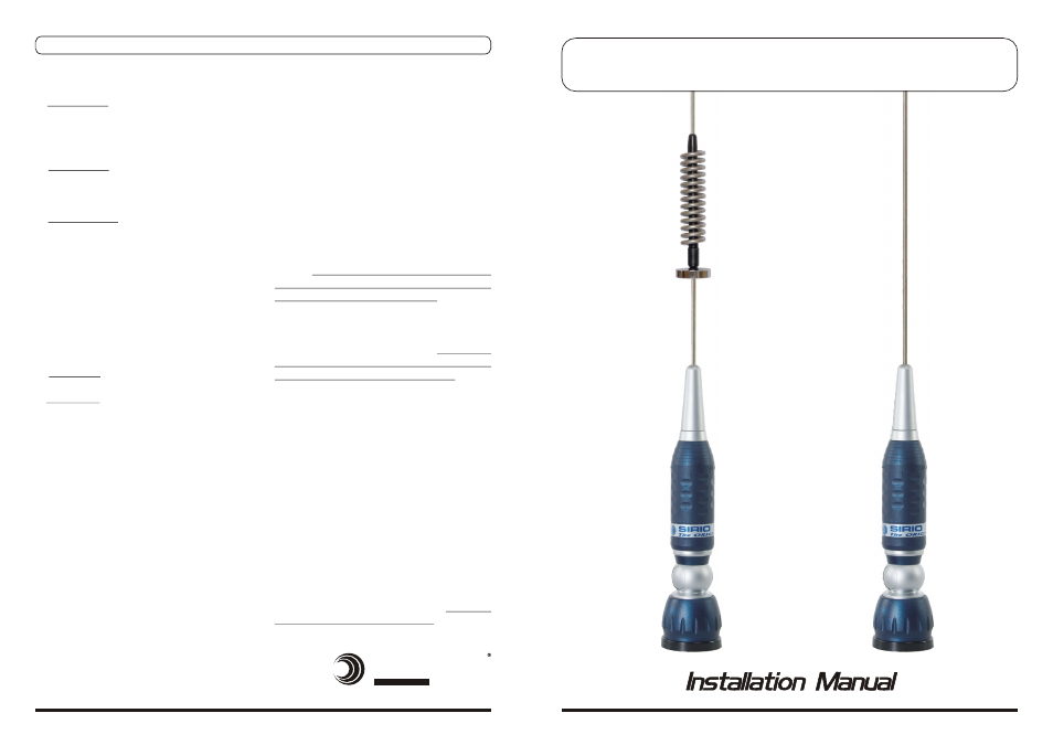
TURBO series Blue Line
TURBO series Blue Line
B) Connect your SWR-meter between the
antenna connector and your CB transceiver
(follow the instructions of your SWR-meter for
the correct use to your equipment).
C) The following procedure is used for the
tuning of the 40 channels CB-band Radio in
the range of:
CH-1 = 26.965 MHz to CH-40 = 27.405
MHz with CH-19 = 27.185 MHz as centre
band for EU Frequencies.
CH-1 = 27.601 MHz to CH-40 = 27.991
MHz with CH-19 = 27.781 MHz as centre
band for UK Frequencies.
Select CH-1 on your CB-transceiver and take
an SWR measurement, writing down the
results. Transmit only for a few seconds
because in case the SWR is too high the
transceiver could be damaged.
D) Repeat the procedure for CH-19 and CH-40
E) If all SWR results are very high (more than 3)
probably there’s a short circuit in the cable or
your antenna is defective. To avoid
damages to your CB transceiver DO NOT
use it until the problem is rectified.
F) If the SWR results are the same on CH-1 and
CH-40 and the lower value is on CH-19, your
antenna doesn’t need any tuning.
G) If the SWR result on CH-1 is lower than CH-
40 your antenna is electrically TOO LONG and
you should slightly cut the radiator by 10mm
at a time. Avoid cutting too much. As long as
you get the same values on CH-1 as well as
CH-40.
H) If the SWR result on CH-40 is lower than CH-
1 your antenna is electrically TOO SHORT and
you need to pull out the radiator as long as
you get the same values on CH-1 as well as
CH-40.
Some antennas can be tuned only by
adjusting special rings, nuts or screws so you
can follow the above procedure but you don’t
need to cut or extend the radiator.
INSTALLATION
1) Hole mount installation
A) Hole Drilling: Chose the position on your
vehicle (centre roof is recommended) and drill
a hole according to the mount diameter.
Please ensure a good electrical ground contact
is made.
B) Connections: Position the cable in your
vehicle shortening its length according to your
needs. Connect the PL259-male to the cable
ready for the connection to the transceiver.
C) Electrical Tests: Ensure there is no short
circuit between the central pin and the nut of
the connector. Ensure there is electrical
continuity of the cable from the central pin
(connector side) to the central contact
(antenna side). Ensure there is electrical
continuity of the cable from the nut (connector
side) to the ground (antenna side)
REMARKS: As some antennas are in short
circuit and it would be impossible to do the test
after the installation, we recommend you test
the cable prior to connecting the antenna.
D) Installation: Pay attention to securing all
screws and nuts during the final installation.
E) Suggestion: After the final installation and
BEFORE connecting your transceiver, we
recommend an electrical continuity check
between the nut of the PL259 and the ground
of your vehicle.
2) Special mounts installation: Follow the
same instructions of Point 1.
3) Magnetic mount installation: Follow the
instructions supplied with the magnetic
mount.
TUNING
Most of the antennas are factory tuned and
don’t need any extra tuning, but in case of fine
adjustments we recommend to follow the
procedure below:
A) To perform a correct test, move to an open
space far from metal parts such as metal doors,
buildings, towers, gates etc. at minimum 50
metres or more.
HI-QUALITY ANTENNAS MADE IN ITALY
antenne
SIRIO
S
TURBO series Blue Line
TURBO series Blue Line
TU
R
B
O
1
0
0
0
(ta
pe
re
d
w
hi
p,
h
ei
gh
t 1
15
cm
)
TU
R
B
O
2
0
0
0
(ta
pe
re
d
w
hi
p,
h
ei
gh
t 1
45
cm
)
TU
R
B
O
3
0
0
0
(ta
pe
re
d
w
hi
p,
h
ei
gh
t 1
71
cm
)
TU
R
B
O
8
0
0
S
(s
pr
in
g
w
hi
p,
h
ei
gh
t 8
4c
m
)